
Resistance welding is the name given to a group of welding processes in which coalescence between two metals is obtained by heat arising out of resistance posed by the work-piece to the flow of current. Pressure is generally applied to secure the joint firmly. The work-piece is a part of the electric circuit, through which the current flows.
Resistance welding has seven different variations: flash welding, percussion welding, projection welding, seam welding, spot welding, upset welding, and high-frequency resistance welding.
Principles of The Resistance Welding
All arc welding are similar to each other in many ways. However, resistance welding is significantly different from the conventional welding processes used in the world today. In this process, no fluxes are used; filler metal is also not used generally.
When electric current passes through two metal pieces, the metal poses resistance to the flow of current. Due to this resistance, heat gets generated in the metal. If the current is high enough, and the resistance is localized enough, adequate amount of heat gets generated to melt the metal pieces. Thereafter, if the metal pieces are pressed together by application of force, the pieces get fused together.
The amperage of the welding current determines the heat generated at the point of welding. Besides this, the time for which the current flows through the metal work-pieces, and the pressure applied between the work-pieces, also have a significant bearing on the strength and soundness of the joint. It is to be noted that the pressure needs to be applied throughout the duration of the welding action, so that an electrical circuit remains established as long as the current flows.
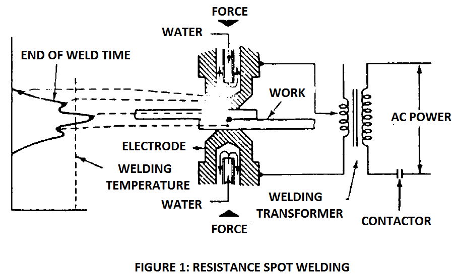
The most common variation of the resistance welding is the spot welding. The process is illustrated in the below figure. Understanding spot welding makes it easy to understand the principle behind the resistance welding.
The voltage, current and the resistance in the resistance welding circuit obey the ohm’s law. As per ohm’s law, V = I x R. Here, ‘V’ is the voltage, ‘I’ is the current flowing through the circuit, and ‘R’ is the resistance offered by the circuit. The highest resistance is offered by the two work-pieces that need to be welded.
The heat generated at the point of welding is calculated by the following formula: Q = V x I x t. Here ‘Q’ is the heat generated in Joules, ‘I’ is the current in amperes, and ‘t’ is the time duration of current flow, in seconds. By applying ohm’s law, this formula can re-written as Q = I2Rt.
Further, it should be understood that the resistance of the work-pieces is not the only resistance available in the welding circuit. There are other elements too, such as electrodes, cables, etc. The resistance of these other elements, albeit small, should also be taken into account.
A factor KC is introduced in the heat calculation for these losses. So the formula reads, Q = I2Rt x K. The factor K represents heat losses on account of resistance by other components of the circuit.
From the above formula, it can be seen that the heat generated is proportional to the square of the welding current. This means that if the current is doubled, the heat generated becomes four times. We can see that the heat generated is also directly proportional to the time of current flow. This means that, if the current is doubled, the time for welding can be reduced by half, and the heat generated would still be double of the original. So a high welding current, small voltage power is supplied by the power source.
It should be understood that some heat gets generated in the other components of the welding circuit too. Notably, the spot where the electrode touches the workpiece poses substantial resistance to the current. Due to this, the electrode gets heated up. So heated up in fact that it has to be cooled by cooling water.
The pressure applied also plays an important part in the quality of the weld. High mechanical pressure results in refined grains of the weld metal. The pressure is applied by a mechanized arrangement – either by hydraulic means, or pneumatic means, or by mechanical means. The resistance welds are generally made at a rapid clip.
The quality of the weld does not depend a lot on the skill of the welder. It depends more on the adjustment of machine, choice of parameters, and adherence to weld procedure. The welder’s skill does not come into play because the pressure, current cycle, time for application of pressure, movement of electrodes, etc. are all controlled by the machine.
All these parameters need to be explained to the machine by way of a program. The resistance welding equipment has inbuilt controls to effect these parameters in accordance with the program fed by the operator.
Applications Of Resistance Welding
Resistance welding processes are utilized by industries that engage in mass production of parts. In such jobs, repeatability and consistency in quality is important because same weld has to be made hundreds of thousands of times. The operator only performs the function of loading and unloading the job, while the machine performs the function of welding.
One major user of this process is the automobile industry. Another major user is the appliance industry. Another user is the steel industry, where this process is used to join manufacturing pipe, tubing and small structural joints. Whenever joining of thin base metals needs to be done on a large scale, resistance welding is a good candidate.
The unique feature of resistance welding is that it does not require filler rods. Also, it produces with consistency a large number of joints, at a rapid pace, while the quality of welds remains high.
Weldable Metals
Most commonly used metals in the industry can be welded with resistance welding processes. Thinner metals are easier to weld than thicker metals. For some of the metals, a post weld heat treatment may be required to obtain the desired mechanical properties.
The following table shows the weldability of commonly used metals with resistance welding.
| Metal | Weldability with resistance welding |
| Low carbon steel | Weldable |
| Low alloy steel | Weldable |
| Medium and high carbon steel | Possible, but not commonly used. |
| Stainless steel | Weldable |
| Alloy steels | Possible, but not commonly used. |
| Aluminum | Weldable |
| Inconel | Weldable |
| Magnesium | Weldable |
| Monel | Weldable |
| Nickel silver | Weldable |
| Nickel | Weldable |
| Precious metals | Weldable |
Weldability
For feasibility of welding (or weldability) a given base metal with resistance welding basically depends on three factors: electrical resistivity, thermal conductivity, and melting point.
The metal needing to be welded must offer high electrical resistance to flow of current, so that high amount of heat can be generated. Then, it must also have low thermal conductivity such the heat thus generated does not get dissipated to the adjoining base metal. Further, the metal must also have a low melting point such that it melts at relatively low temperatures.
Iron based with low alloying content fall into this category.
The entire principle of resistance welding depends on the resistance offered by a metal to the flow of current. Resistance in turn depends on resistivity of the metal, which is a property of the metal. Resistance and resistivity are related by the formula: R = ρ x L/A, where ρ is the resistivity of the metal, ‘L’ is the length of the conductor, and ‘A’ is the cross section area of the conductor.
Metals that have low resistivity and slightly higher thermal conductivity are therefore difficult to weld with resistance welding. The heat generated at the point of welding quickly gets thermally conducted to other parts of the base metal. Such metals are magnesium, aluminum, etc. Likewise, precious metals have quite high thermal conductivity. It is thus difficult to weld precious metals too, with resistance welding.
Another category is the refractory metals. These metals have very high melting points. So a very high current would be required to melt the metal with resistance-induced heat.
The three factors: resistivity, conductivity, and melting point can be combined into a formula that can be used as an indicator. This indicator indicates the relative ease with which a base metal can be welded with resistance welding. Note that the result of this formula indicates only relative ease, while comparing between metals. This formula is W = ρ x 100/(T x K).
In this formula, ‘W’ is the weldability. ‘K’ is the relative thermal conductivity with respect to copper, ‘T’ is melting point temperature in °C, and ‘ρ’ is the resistivity. All three are properties of the metal. If, for a metal, ‘W’ is lower than 0.25, the weldability is considered poor. If it falls in 0.75 to 2 range, it is considered good. Any value above two is considered excellent.
When used in this formula, mild steel would have rating of above 10. Aluminum would have rating between 1 and 2. The rating would differ based on the alloying content in the metal. The weldability of copper and certain brasses is poor.
This was about resistance welding. Please share your thoughts in the comments section below.