
CAW – short for carbon arc welding, is a welding process in which fusion is obtained by heat produced by striking an arc between a carbon electrode and the work-piece. Shielding is not used. Pressure may or may not be used. Filler rod also may or may not be used.
The main difference between the carbon arc and metal arc welding is the electrode. Metal arc welding makes use of a metal electrode, while carbon arc welding – as the name suggests – makes use of carbon electrodes.
Carbon Arc Welding Equipment
The following paragraphs discuss in brief about the electrodes used in CAW, machines, welding current and welding circuit.
Electrodes In Carbon Arc Welding
The electrodes in CAW are made of carbon. Similar to the SMAW process, the electrodes are held in electrode holders. The carbon electrodes come in two types: baked carbon electrodes and graphite electrodes. Graphite electrodes produce a ‘soft’ arc that makes less noise and easy to control. The baked electrodes make for a slightly noisy operation, but these electrodes last longer.
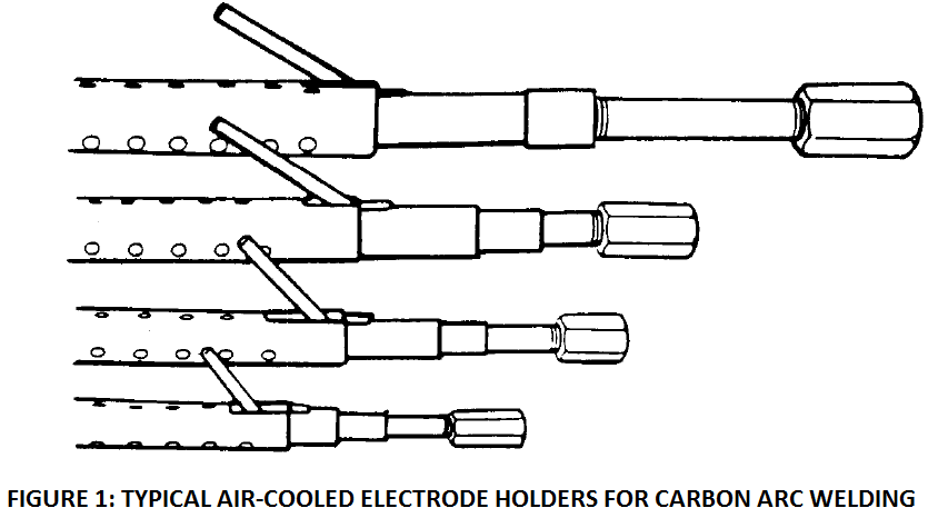
The sizes of these electrodes vary from 1/8 inch to almost 5/16 inch (3.2 mm to 8 mm). The larger size electrodes require use of water-cooled electrode holders. The figure below illustrates typical air-cooled electrode holders.
Machines
Direct current is generally used for carbon arc welding. The power source is a rectifier type.
Welding circuit and welding current
The welding circuit of single-electrode carbon arc welding is similar to that of shielded metal arc welding. The electrode is generally connected to the negative terminal of the power source. In other words, DCEN polarity is used. This is especially so when single electrode CAW is employed. This is done so as to keep the concentration of heat on the work-piece (instead of electrode).
If the electrode is connected to the positive terminal, more heat would be generated at the electrode tip. This can cause erosion of carbon electrode, and possibly introduce carbon in the weld metal as well, which is highly undesirable. This also causes black smoke near the arc.
The power source is generally a constant current type, characterized by drooping current-voltage characteristics. A power source of 60% duty cycle is employed. The machine has a voltage rating of 50 volts since this much voltage is required for carbon arc welding of copper.
Alternating current is normally not used for single electrode carbon arc welding. This is because the rapidly changing polarity in AC brings positive polarity to the electrode tip, which can cause erosion of carbon electrode. This not only means that the electrode has to be frequently adjusted at the holder (such that a minimum 3 to 5 inches of electrode protrudes from the holder towards the work-piece), but there are chances of introducing carbon in the weld metal as well.
The electrode holder for CAW is slightly different from the one used in SMAW. Typical electrode holders are shown in figure 1 above. The carbon electrode becomes extremely hot during use.
Other than the above few aspects, the welding circuit of single-electrode CAW is largely similar to that of SMAW process.
Major Uses Of Carbon Electrode Welding
The single electrode method is not used widely, any longer. It is used only for a few applications. One of its’ uses for welding copper. Another use is welding of galvanized iron. This article in later paragraphs lists some recommended welding parameters for galvanized steel.
At lower base metal thicknesses, the process is used without a filler rod, that is – autogenously. At higher thicknesses, a filler rod is used. The filler rod is used to add weld metal to the weld puddle, by introducing it between the arc and base metal.
Carbon arc welding process can be used for making out of position welds as well.
Weldable Metals
Carbon arc welding is appropriate for welding of materials that do not get affected by carbon pickup in the weld puddke. Due to the carbon electrodes, evolution of carbon monoxide and carbon dioxide during the welding process is significant. The process is suitable for materials that are not affected by these gases.
The process is used for both ferrous and non-ferrous metals, and for welding both groove welds and surfacing welds. The following paragraphs discuss very briefly welding of steel, cast iron and copper using this process.
Steels
CAW is used for making autogenous welds in edge joints between thin sheet metals. The edges of the work-pieces are fitted closely together, and fusion is achieved using CAW, without use of a filler metal.
Another use is braze welding of galvanized steel. A bronze welding rod is used for the purpose. The arc should be directed at the filler rod (instead of the work-piece). This is done to protect the galvanizing coating. The arc is struck at the electrode or a run-on plate. Low amperage, high travel speed, a low voltage (a low arc gap) is used so that the heat input remains low. The melted filler rod is deposited on the galvanized steel.
Cast Iron
Cast iron can be welded with carbon arc welding. A preheat of 1200°F (650°C) should be used so that rate of cooling is kept low. This is necessary if the metal has to undergo any further fabrication activity such as welding or machining. If the rate of cooling is not kept low, the resulting weld metal would be very hard.
Copper
As mentioned above, single electrode carbon arc welding is used for welding copper. The polarity used for this welding is DCEN. DCEP is avoided, because – as explained in the above paragraphs – positive polarity at electrode causes concentration of heat at the electrode tip. This, in turn, may cause erosion of the carbon electrode, and increases the unwanted possibility of carbon introduction in the weld metal.
A preheat of 300°- 600°F (150° C – 650°C) should be used, based on the thickness of the base metal. Preheating is necessary because the thermal conductivity of copper is very high . This causes heat from the welding zone to be dissipated to the adjoining base metal very rapidly.
A long arc length is used so that carbon from the electrode gets a chance to combine with oxygen and form carbon dioxide. The carbon dioxide provides some shielding to the molten metal from the atmospheric gases. A root gap of 1/8 inch (3.2 mm) is recommended, and a high travel speed should be used.
Principles of Operation
The following figure illustrates the principles of carbon arc welding, showing a single carbon electrode. As can be seen, an arc is initiated between a carbon electrode and the work-piece. The heat of the arc heats the base metal and creates a weld pool. The filler metal is fed into the arc, such that it melts and deposits weld metal. As this pool solidifies, weld metal is produced.
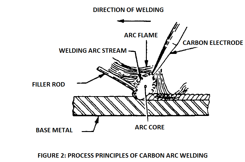
The shielding of the arc from atmospheric gases is provided by carbon dioxide that evolves as a result of arc. The high temperatures of the arc cause the carbon available in the electrode to react with oxygen and produce carbon dioxide as the product. The carbon electrode undergoes rapid erosion due to this.
The carbon dioxide thus produced displaces atmospheric gases from the region surrounding the arc, thus protecting the weld metal from oxidation.
Similar to GTAW, filler rod is separately manually fed into the weld pool such that it melts and gets deposited as weld metal. The filler rod is fed with one hand, while the other hand is used to manipulate the arc. As the arc moves along the direction of welding, the arc is kept directed at the base metal, while the filler rod is fed into the pool. The speed of travel and the frequency of feeding the filler into molten pool determine the shape and size of the resulting weld bead.
The composition of the filler depends on the composition of base metal. For brazing and braze welding, bronze filler metal can be used.
In order to obtain a good weld, like all other welding processes – cleanliness of the base metal from sorts of contaminants is important. There should not be any dirt, oil, grease, etc. on the surface of the base metal at the time of welding. The work-pieces should be clamped together securely, and be tack welded.
Carbon arc welding is a very old method of welding, and does not find wide industrial usage today.
The work-pieces must be free from grease, oil, scale, paint, and other foreign matter. The two pieces should be clamped tightly together with no root opening. They may be tack welded together.
The carbon electrodes come in various sizes, ranging from 1/8 inch (3.2 mm) to 5/16 inch (8 mm). The size has to be chosen based upon the thickness of the base metal. The tip of the electrode should be tapered to strike the arc. The free length of the electrode that protrudes from the electrode holder should be 4 to 5 inches (100 mm to 125 mm approx.).
The arc is struck, in a manner similar to shielded metal arc welding, by touching the electrode on the work-piece, and immediately retracting it to the required arc length. An arc length of ¼ inch (6.4 mm) to 3/8 inch (9.5 mm) gives the best results. The arc length should be just right. Too short an arc length causes excessive carburization of the molten metal, and a too high arc length causes an unstable arc that does not yield a quality weld.
If the arc gets extinguished for any reason, it should not be restarted at the same point where it broke off. This would cause a hard spot to form at that location. Instead, the arc should be restarted a little away, after which it can be brought back to the intended area.
The size of weld puddle in CAW is larger than that in other processes such as, say GTAW process. Due to large size, it is difficult to weld in overhead and vertical welding positions. When welding of thin base metal thicknesses, backing should be used to minimize the chances of burn-through.
Welding Schedules
The following table indicates the recommended welding parameters for welding of various thicknesses of galvanized iron, using a silicon bronze filler metal. A short arc length should be used so that no harm reaches the galvanizing layer. Also, the arc should be directed at the filler rod instead of at the base metal.
Welding Parameters For Braze Welding Of Galvanized Steel
| Material thickness | Material Gauge | Carbon electrode size | Filler rod size | Welding current (DC Amps) | Arc Voltage (volts) (DCEN) |
| 0.024 inch (0.6 mm) | 24 | 3/16 inch (4.8 mm) | 3/32 inch (2.4 mm) | 25-30 | 13-15 |
| 0.030 inch (0.8 mm) | 22 | 3/16 inch (4.8 mm) | 3/32 inch (2.4 mm) | 25-30 | 13-15 |
| 0.036 inch (0.9 mm) | 20 | 3/16 inch (4.8 mm) | 3/32 inch (2.4 mm) | 30-35 | 14-16 |
| 0.048 inch (1.2 mm) | 18 | ¼ inch (6.4 mm) | 1/8 inch (3.2 mm) | 30-35 | 14-16 |
| 0.060 inch (1.5 mm) | 16 | ¼ inch (6.4 mm) | 1/8 inch (3.2 mm) | 30-35 | 14-16 |
| 0.075 inch (1.9 mm) | 14 | ¼ inch (6.4 mm) | 1/8 inch (3.2 mm) | 30-35 | 14-16 |
| 0.105 inch (2.7 mm) | 12 | ¼ inch (6.4 mm) | 1/8 inch (3.2 mm) | 35-40 | 15-17 |
Welding Parameters For Carbon Arc Welding Of Copper
The following table indicates the recommended welding parameters for carbon arc welding of various thicknesses of copper.
| Material thickness | Carbon electrode size | Filler rod size | Welding current (DC Amps) | Arc Voltage (volts) (DCEN) |
| 1/16 inch (1.6 mm) | 3/16 inch (4.8 mm) | 1/8 inch (3.2 mm) | 90 | 40 |
| 5/64 inch (2.0 mm) | 1/4 inch (6.4 mm) | 5/32 inch (4.0 mm) | 120 | 40 |
| 3/32 inch (2.4 mm) | 1/4 inch (6.4 mm) | 5/32 inch (4.0 mm) | 135 | 40 |
| 7/64 inch (2.8 mm) | 1/4 inch (6.4 mm) | 5/32 inch (4.0 mm) | 140 | 40 |
| 1/8 inch (3.2 mm) | 1/4 inch (6.4 mm) | 3/16 inch (4.8 mm) | 150 | 45 |
| 9/64 inch (3.6 mm) | 1/4 inch (6.4 mm) | 3/16 inch (4.8 mm) | 160 | 45 |
| 5/32 inch (4.0 mm) | 1/4 inch (6.4 mm) | 3/16 inch (4.8 mm) | 165 | 45 |
| 11/64 inch (4.4 mm) | 1/4 inch (6.4 mm) | 3/16 inch (4.8 mm) | 170 | 45 |
| 3/16 inch (4.8 mm) | 1/4 inch (6.4 mm) | 3/16 inch (4.8 mm) | 185 | 45 |
| 13/64 inch (5.2 mm) | 5/16 inch (7.9 mm) | 1/4 inch (6.4 mm) | 200 | 45 |
| 7/32 inch (5.6 mm) | 5/16 inch (7.9 mm) | 1/4 inch (6.4 mm) | 200 | 45 |
| 15/64 inch (6.0 mm) | 5/16 inch (7.9 mm) | 1/4 inch (6.4 mm) | 205 | 45 |
| ¼ inch (6.4 mm) | 5/16 inch (7.9 mm) | 1/4 inch (6.4 mm) | 215 | 45 |
| 17/64 inch (6.7 mm) | 5/16 inch (7.9 mm) | 1/4 inch (6.4 mm) | 225 | 45 |
| 9/32 inch (7.1 mm) | 5/16 inch (7.9 mm) | 5/16 inch (7.9 mm) | 250 | 50 |
| 5/16 inch (7.9 mm) | 5/16 inch (7.9 mm) | 5/16 inch (7.9 mm) | 250 | 50 |
| 11/32 inch (8.7 mm) | 5/16 inch (7.9 mm) | 5/16 inch (7.9 mm) | 255 | 50 |
| 3/8 inch (9.5 mm) | 5/16 inch (7.9 mm) | 5/16 inch (7.9 mm) | 270 | 50 |
| 13/32 inch (10.3 mm) | 5/16 inch (7.9 mm) | 5/16 inch (7.9 mm) | 290 | 50 |
| 7/16 inch (11.1 mm) | 3/8 inch (9.5 mm) | 3/8 inch (9.5 mm) | 300 | 50 |
| 15/32 inch (11.9 mm) | 3/8 inch (9.5 mm) | 3/8 inch (9.5 mm) | 310 | 50 |
| ½ inch (12.7 mm) | 3/8 inch (9.5 mm) | 3/8 inch (9.5 mm) | 325 | 50 |
Welding Currents For Carbon Electrodes
The following table indicates the recommended amperage for different diameters of baked carbon electrodes and graphite electrodes.
| Electrode Size | Amperage for carbon electrodes | Amperage for graphite electrodes |
| 1/8 inch (3.2 mm) | 15-30 | 15-35 |
| 3/16 inch (4.8 mm) | 25-55 | 25-60 |
| ¼ inch (6.4 mm) | 50-85 | 50-90 |
| 5/16 inch (7.9 mm) | 75-115 | 80-125 |
| 3/8 inch (9.5 mm) | 100-165 | 110-165 |
| 7/16 inch (11 mm) | 125-185 | 140-210 |
| ½ inch (12.7 mm) | 150-225 | 170-260 |
| 5/8 inch (15.9 mm) | 200-310 | 230-370 |
| ¾ inch (19 mm) | 250-400 | 290-490 |
| 7/8 inch (22.2 mm) | 300-500 | 400-750 |
Variations Of The Process
There are mainly two variations of carbon arc welding. One, carbon welding with twin-carbon electrodes. Two, carbon arc gouging and cutting.
Twin-electrode Carbon Arc Welding
In this variation, as the name suggests – two carbon electrodes are used instead of one. The arc is struck between these two electrodes. The electrode holder is specially made for this process, such that it can host two electrodes at a time. Like the single electrode version, filler may be used or may not be used. This process is also used for brazing. This process does not offer any particular advantages over other commonly used welding processes. The process is quite slow, and therefore not used extensively in industry.
The two electrodes protrude equally from the holder. One of the electrodes is movable, while the other does not. Both electrodes are attached to the holder through screws. When the movable electrode is brought close to the other electrode, the arc is struck. The heat of this arc is used to create a puddle of molten metal.
The electrodes are placed at such an angle that the arc thus generated points away from the junction of two electrodes, and points towards the work-piece. The arc is ‘softer’ than the one produced using a single electrode CAW. The temperature of this arc produced in the twin electrode CAW varies between 8000°F to 9000°F (4427°C to 5000°C).
Unlike the single electrode CAW which can only be operated with direct current, the twin electrode can function with alternating current as well. With AC, both the electrodes disintegrate at equal rates. When direct current is used in twin electrode setup, one of the electrodes (the one connected to positive terminal) should be one size higher than the other (since it disintegrates faster) so that both the electrodes get consumed at an equal rate.
The twin electrode CAW can be used not only for welding, brazing, etc., but also for other applications that require heating of the part. For example, it can be used as a source of heat on the OD of pipes that require bending, or other similar parts that require forming. The following table indicates welding parameters for different base metal thicknesses, when twin-electrode carbon arc welding is used.
| Base Metal Thickness | Carbon Electrode Diameter | Welding Current (Amps) | Voltage (volts) |
| 1/16 inch (1.6 mm) | ¼ inch (6.4 mm) | 55 | 35-40 |
| 1/8 inch (3.2 mm) | 5/16 inch (7.9 mm) | 75 | 35 |
| ¼ inch (6.4 mm) | 3/8 inch (9.5 mm) | 95 | 35 |
| Above ¼ inch (above 6.4 mm) | 3/8 inch (9.5 mm) | 120 | 35 |
Carbon Arc Cutting
In this process, the same principle that is used for welding using carbon electrode is used for cutting of metals. Like gas cutting, the heat of the arc melts the metal which falls due to the action of gravity. Higher thicknesses require greater heat input for this cutting action. Also, metal of higher strength and hardness require greater heat inputs.
Like twin-electrode CAW, carbon arc cutting is also not used widely in the industry. This is because the quality of the cut obtained is not too good. A ragged cut edge is obtained. In comparison, gas cutting produces sharper cut edges. Also, this process is quite slow. Hence it is only used when equipment for other cutting processes is not available.
This was about carbon arc welding. Please share your observations in the comments section below.
Excellent article. Such a useful technology to heating, brazing, soldering and even welding. Sure wish it was revived and the rods were still made here in the us. Home hobbyists would love this tech. Great for making home forges as well.