
In order to understand about the polarity in an arc welding circuit, it is first important to understand the construction of the arc welding circuit. This article discusses a few terms used in any electrical circuit such as EMF, current, and resistance. The later part of the article equates the welding electrical circuit to ordinary electrical circuit, and discusses about polarities: straight and reverse polarity.
Components of Electrical Circuit
The arc welding circuit is similar to the ordinary electrical circuit. The ordinary circuit consists of a driving force, which in this case is the electromotive force ( EMF), or the voltage (V), measured in volts. The voltage difference between any two points in the circuit determines the driving potential available to force the current flow between those two points.
The second is the flow. In an electrical circuit, the flow is that of electrons. Rate of flow of electrons is called current (I). This is measured in amperes.
The third component in the electrical circuit is the resistance (R). The unit of measurement of resistance is ohms. Every component in the circuit poses some resistance to the current flow.
When a component allows current to flow through itself easily, it indicates that its’ resistance is low. If it allows little current to pass, it indicates that its’ resistance is high. The resistance posed by a component depends upon its’ inherent character (that is, resistivity), its’ cross sectional area, and the length across which current needs to flow.
Normal Electrical Circuit
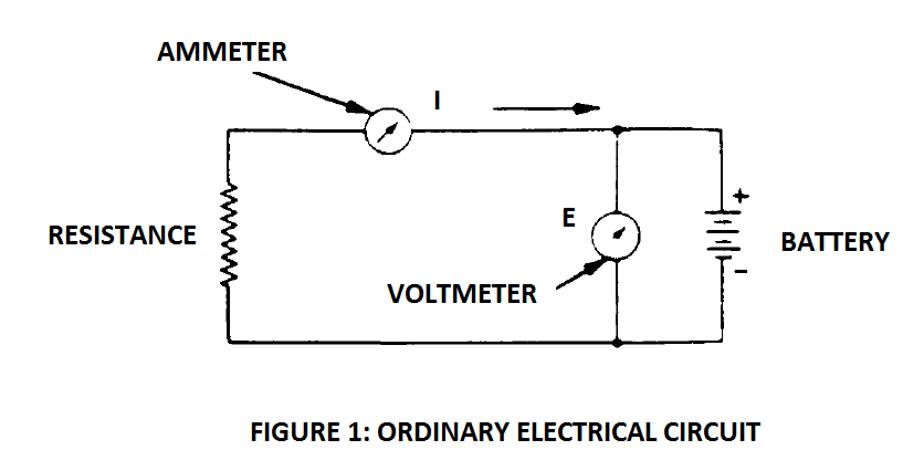
The figure below shows an ordinary electrical circuit. It shows one ammeter that measures the rate of current flow in amperes, a voltmeter that measures voltage across the circuit in volts, and a battery that supplies the power. The longer line of the battery indicates the positive terminal. The current, that is – the electrons (being negatively charged) flow from the negative to the positive terminal.
The direction of flow of current is indicated in the figure. The resistance offered by the circuit to the current flow is indicated by the zigzag symbol. The resistance can be measured by an ohmmeter.
It should be kept in mind that an ohmmeter should not be used to measure resistance in a circuit when current is flowing.
Arc Welding Circuit
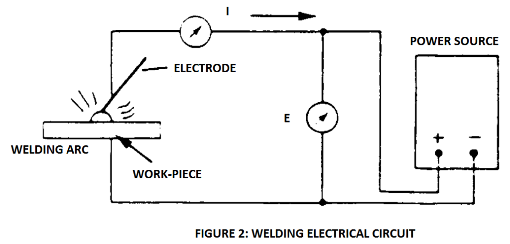
The electrical circuit of an arc welding machine, in barest terms, is same as the electrical circuit described above. Consider the figure 2 below. The battery has been replaced with a generator, or the power source. The power source supplies the potential required to drive current through the cables and to the arcing point.
The resistor has been replaced by the welding arc, as the arc is the main source of resistance. A higher arc length poses greater resistance to current flow.
The flow of current in this circuit too is from the negative terminal of the power source to the positive terminal.
Polarity In The Welding Circuit
In the earliest days of arc welding, the welding used to be done with a bare wire. The wire would be connected to the negative terminal and work to the positive terminal. Since the current flows from the negative to the positive terminal, this connection would yield 65-75% heat on the work-piece (as opposed to the electrode).
Higher amount of heat on the work-piece would mean deeper penetration of the weld.
This connection was termed as the straight polarity. In this, the electrode is connected to the negative terminal, while the work-piece is connected to the positive.
Overtime, it was realized that this concentration of heat on the work-piece is not always good. In case of welding of non-ferrous metals and cast iron, it is problematic if most of the heat is directed at the work-piece. This results in a larger weld pool, which invites hard microstructures in metals such as cast iron.
Therefore, for such cases where it is desired to minimize the heat on the base metal, a practice began to connect the work-piece to the negative terminal, and electrode to the positive terminal. This polarity is opposite of the earlier practice; hence it began to be called as reverse polarity.
Moreover, when covered electrodes came to be in vogue, it was found that they gave the best results under reverse polarity. Hence, slowly – the reverse polarity came to be accepted as an equally acceptable option, based on the need of the base metal and process.
In reverse polarity, as discussed above – electrode is connected to positive, and work-piece is connected to the negative terminal. This polarity is also called DCEP, short for direct current electrode positive.
Conversely, in straight polarity – electrode is connected to negative polarity, and work-piece to positive polarity. Hence, this polarity is sometimes also referred to as DCEN, short for direct current electrode negative.
How To Change The Polarity?
In the earlier times, the machine would have two terminals – one positive, and the second negative. The cables headed to work-piece and electrode would be connected to these terminals in accordance with the desired polarity.
When it was required to change the polarity, the cables would need to be disconnected and interchanged at the terminals.
In modern machines, a polarity switch is provided which accomplishes this task by simply flicking a switch. This switch is called polarity switch. With this switch, the welder can quickly change the polarity of the current.
Other Aspects Of The Welding Circuit
The ammeter in a welding circuit is connected across a high current shunt in the welding circuit. It is basically a millivoltmeter, calibrated to deliver readings in amperes. The shunt is a conductor with very low resistance.
The voltmeter measures the voltage delivered by the machine. This voltage is same as the one that exists across the welding arc.
When welding is not under progress, the voltmeter measures voltage across the machine with no current flowing. This voltage is called open circuit voltage, or OCV. The OCV is higher than the voltage observed during welding.
Another important aspect of an arc welding circuit is the power output of the machine. The power output can be computed by multiplying current and voltage. The result would be obtained in watts. Power can be directly measured too, through a wattmeter. A watt meter is a combination of ammeter and voltmeter, and delivers readings in watts.
The amount of energy or work delivered by the machine can also be computed by multiplying power with the time for which the power was delivered. This work/energy is expressed in terms of joules, or kilowatt-hour.
This was about the arc welding electrical circuit. Please share your thoughts in the comments section below.